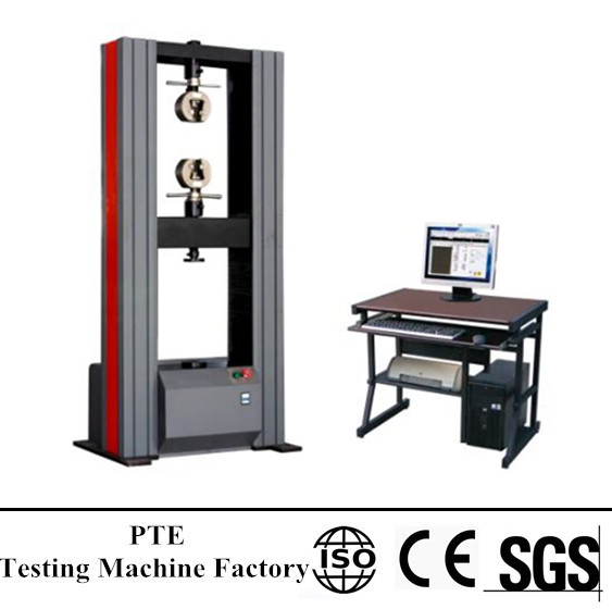
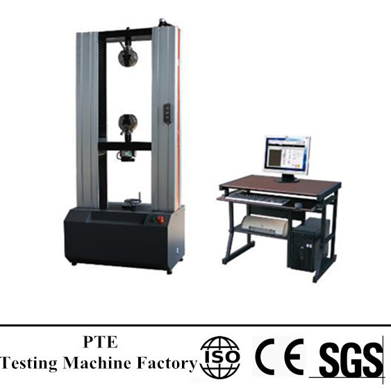
-Universal Testing Machine, Impact Testing Machine-
charpy impact test machine diagram
June 1, 2022charpy impact machineCharpy Impact Test Machinecharpy impact test machine costcharpy impact test machine diagramcharpy impact test machine for salecharpy impact test machine pricecharpy test machinedigital impact testing machineimpact energy testing machineimpact load testing machineimpact test machinesimpact tester machineimpact testing equipmentimpact testing machineimpact testing machine costimpact testing machine experimentimpact testing machine lab manualimpact testing machine manufacturersImpact Testing Machine Priceimpact testing machine price in indiaimpact testing machinesizod impact test machine priceIzod Impact Testing Machineizod impact testing machine manufacturerspendulum impact test machinePendulum Impact Testing Machineplastic impact testing machine
charpy impact test machine diagram
Impact Testing Machine are mainly used to determine the anti-impact capability of metal materials under dynamic load.
Carry out the functions of zero clearing and automatic return, capturing the value of lost impact energy and pendulum cycle by means of setting up with computer program,and the results can be monitored, stored and printed out. Control box or computer program control is alternative operating method.
Technical Specification:
| Model | JBW-300B | JBW-500B | JBW-700B |
| Display | Computer Display semi automatic | ||
| Min reading value | 1 J | 2J | |
| Impact energy | 150/300J | 250/500J | 500/750J |
| The distance between the
pendulum shaft and impact point |
750mm | 800mm | 850mm |
| Impact speed | 5.2m/s | 5.4 m/s | 5.9 m/s |
| Pre-rising angle of the pendulum | 150° | ||
| Specimen bearer span | 40+0.2mm | ||
| Round angle of bearing jaw | R1.0-1.5mm | ||
| Round angle of impact blade | R2.0-2.5mm,(R8mm) | ||
| Thickness of impact blade | 16mm | ||
| Angle accuracy | 0.1° | ||
| Standard specimen dimension | 10mm×10mm×55mm | ||
| Sample box capacity | 10 pcs | ||
| Power supply | 380V, 50Hz , 3 wire and 4phrases | ||
| Dimensions (mm) | 2124x600x1340 | 2200×650×1960 | 2450x1200x2455 |
| Net Weight (kg) | 450 | ||
Maybe you like also
Copy©2017 | China testing machine manufacturers| Sitemap


 universal testing machine working
 working of universal testing machine
 what is universal testing machine